
Contents
- What You Will Need
- Background Around Naiads & Valkyrie
- Haulout Prep & Ordering from Naiad
- Disassembly of the Stabilizers
- Beautification (AKA: New Paint)
- Assembly of the Stabilizers
- Lessons Learned
What You Will Need
This is the list I recommend you will need for a standard seal replacement procedure. If you are planning a full rebuild, additional parts and tools will likely be needed from Naiad.
- A really big torque wrench (This is the one I purchased and used to take the stabilizer bolts off)
- A 12″ or 13″ extension drive for the 6 sq-ft fins (What I purchased to take the stabilizer bolts off)
- A 1-3/8″ hex drive socket (What I purchased to take the stabilizer bolts off)
- The Naiad manual fin removal tool
- RTV Adhesive/Sealant (for making a water tight seal of metal components and rings)
- Waterproof grease for the inner part of the sealing rings
- Tool picks for pulling out old stubborn RTV sealant
- Break parts cleaner for keeping a clean finish on metal prior to new sealants
- If rebuilding the entire thing like I did, order a case of this stuff, no joke.
- (optional, but recommended) Extra screws for the inner retaining plate. They are small and easy to lose.
Background
This post documents my experience with rebuilding my Naiad model 201 stabilizers installed on my boat Valkyrie. It is not an official how-to, but I hope perhaps it helps someone out there.
In order to reduce side to side rolling while underway, Valkyrie has a pair of Naiad model 201 stabilizers, one on each side of the boat, which drastically help to reduce roll. These are largely considered ‘low maintenance’ methods of controlling roll – with alternatives being different brands all doing a similar mechanical function, and a manual pair of ‘fish’ that are cabled to a pair of outriggers and launched manually on off both sides of the boat. One thing I found – she does need something to control roll even when things are just a little rough.
While in my research phase well before purchasing Valkyrie, I looked into the different stabilized options of Nordhavns. The mechanical options seem to be largely preferred with one of the major drawbacks being the need to haul out every few years and replace the seals, and dealing with the maintenance of the system every few years. Several blogs out on the internet document the process and a few highlight the ‘nightmares’ that come with an unmaintained system. This post, will likely air on the nightmare side of things.
During the purchase of Valkyrie I was made aware that the previous owner did not maintain the seals on a regular basis like the manufacturer recommends. I Assumed there was some wiggle room here in terms of replacement dates and and I had a bit of time to get it scheduled sooner, rather than later. Without having the ability to take them apart I did the best my novice eye could to judge their water tightness, and the survey and sea trial found no leaks or water intrusion, although they did show their age just in appearance.
Fast forward to post-purchase, I am several miles off-shore bringing Valkyrie to her new berth, and the stabilizers are hard at work. Unfortunately for me, that also meant now that they were moving considerably, it was obvious there was a failure of the seals, and water was intruding into the housing which should be normally packed full of grease. A lesson learned for any future owner of a stabilized trawler, make sure you get into some rougher water, or at least cross several wakes, to get those things moving and see if there is water issues if you suspect it.
The audience for this post is small, yet I hope it can provide some insight into someone who may own a Naiad stabilized boat, since the Naiad 201, Naiad 252, and others are all built in a very similar way.
I have a small rant below, but if you are looking for more technical details of the disassembly and reassembly, skip to the appropriate sections following the rant.
Note – This is NOT an official guide and is just what I discovered on my own while working on my own boat.
Haulout Prep & Ordering from Naiad
Working with Naiad Dynamics was one of the worst customer support experiences I have ever dealt with in my adult life.
That sentence must be first. I cannot understand how overwhelmingly difficult it was to get reliable support from this company, and I have officially sworn them off from any future boat purchase because of it. Considering the money I was planning on spending, there was one point in the journey I seriously considered (and started) researching competitors so I could rip their system out and email the CEO the receipt of the money I gave their competition. Overall, I found them infuriating.
During the journey from Massachusetts to North Carolina to transport Valkyrie to her new berth, one of the hydraulic lines that runs the stabilizers blew, and sent motor oil (which is used as hydraulic fluid) everywhere. It added a lot of cleanup and all new hoses to the parts list, but also meant the stabilizers would be inoperable and I would need to work on these someplace close to home. I spent a few weeks looking for yards within about a days cruise that could work on it, but none had any experience with this system. An engineer by trade, I feel confident in my own mechanical skills, so I opted to do the work myself, and planned a month on the hard to rebuild the system, and do some other work on the boat.
My emails to Naiads support alias were regularly ignored. Getting frustrated I called multiple offices (Maryland and Florida) and didn’t get a call back. Eventually one called me and told me only their Connecticut office dealt with the parts and support I needed. Calling them direct, I eventually made it though.
The tech I worked with was David – He has been there a long time because my Naiad booklet that came with my boat had his name and phone number hand written on the cover, so clearly previous owners worked with him before. David had a hard time letting me do the work on my boat, despite my problem that there were no yards near by that did this work, nor was there one that I could easily take the boat to over several days considering I had no hydraulics to run the system.
Once it was determined I planned to do this work myself, David routinely ignored my emails and rarely, if ever, returned my phone calls. He told me any parts I needed would take at least 3-4 weeks to ship, which considering my haulout time of approximately 1 month now left me in a dilemma – Do I order some additional parts I may need at extra costs? or risk going without and leaving things half-assembled for nearly a month (plus the additional storage fees I am paying the boat yard) if I need to order on the fly?
Even trying to order the parts (with extras to save on time) was nearly impossible, and it was not until David was out of the office that I was redirected to a co-worker of his who not only responded quickly, but had the parts out the next day on a ground shipment! Turns out there was no 3-4 week delivery time, and all the parts were in stock and ready to go (This was an order of nearly two dozen parts consisting of extra screws, seals, seal retaining hardware, bearings and races, and more). After all was said and done, some of the spare parts I did not necessarily need (such as the large metal shaft housing) and would have cleaned up just fine, but ohh well, chock this up to the pains of boat ownership.
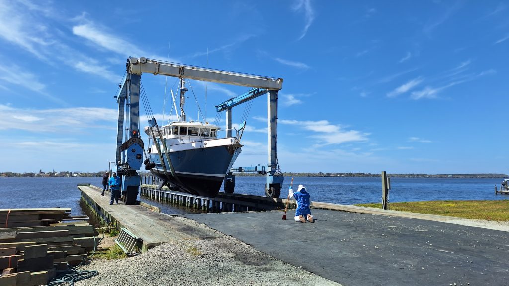
Naiad drama aside – It took some searching to find a yard that would haul me around late March, early April since I planned on living on the boat on the weekends to do this work, and take advantage of the spring time weather before it got blisteringly hot. Fortunately, one was found relatively close by and the haul went without any major issues.
Disassembly
Working on the system is split up in two different areas – the inside, and the outside/housing assembly.
Before any work could begin, I started by using the locking pin to put the fins in a “center” position before popping them off using the special manual tool provided by Naiad (at significant cost as well, totaling around $1000 for a threaded chunk of steel). This was a lot easier than I expected. The bottom of each fin has a large rubber stopper. Using a pocket knife I pried it open to reveal a hollow tube leading to the pin holding the fin in place.
I had already purchased a large torque wrench capable of going to around 600 ft. lbs, and this had a handle that was about 3 feet long. Combined with a 12″ extension bar I was able to easily remove the 1-3/8″ hex bolt holding things tight, 4 bowed washers (with the bow facing toward the bolt head) came with it.
The fin was still on the shaft using pure friction at this point, so the special tool from Naiad was now threaded in place and a makeshift wooden table was built a few inches under the fin to catch it as it fell. Once the friction fit is broken, the fin will drop to the ground, and weighing at least 100 lbs, you want to make sure you have something solid to catch it that isn’t a person.
The weight of the fins, combine with the odd angle of the boat and its closeness to the ground make them difficult to handle solo. The problem with the table approach is that once the fin is dropped, you needed one person to hold it back up so the other person could remove the table. Once removed, both people could lower it down the shaft which was about 12-16 inches.
In hindsight, next time I need to pop the fins I’ll be making a custom A-Frame to help with this activity significantly and make it a lot easier for a solo person to do. If you are planning this yourself, here is a rough idea of what I think would work.
- Build two A-frames out of 2x4s with a door hinge or something up top to make their angle adjustable. Mount them about 18″ apart so it becomes one large A-Frame. Using rope and spare screws, use screws to make cleats to tie the rope to in order to adjust the stance of the A-frame.
- At the top of the large A-frame on the side that will handle the fin, install a strong cross-member and mount a block and tackle. Keep it flush from the face of the A-frame.
- UIsing a piece of plywood that is about 18″ tall and wide enough to go across the width of your two A-frames, with 2×4 members on the outside to act as guiding rails, create a sled that rides along one half of the A-frame. To the top of this sled mount the other half of the block and tackle.
- The sled should have a strong lip made of 2×4’s sticking out 6-8 inches (think two pieces of 2×4 sticking out on either edge of the sled. This should be hollow in the center to allow your tools to access the bolt.
- A single block may be needed mounted near the bottom of the a-frame, and mounting the block and tackle in a way that you can pull the shaft back up later will require the rope you pull to be located in the bottom of this assembly since the fin will be in your way.
- Or if you feel strong enough, use the sled to let it slide down or push it up when remounting, and just use a free hand and screw gun to screw it in place.
With the above A-Frame, you could snug it up to the fin to match the angle from the boat and have the lip to catch it just an inch or two below the fin. Once off, the pulley will make it easy to lower from the shaft as a single person. Had this not been a complete rebuild, you could leave the fin on the sled, take off the retaining bracket holding the old seals in place, replace them, and then use the pulley to pull the fin back up and snug it onto the shaft with minimal effort.
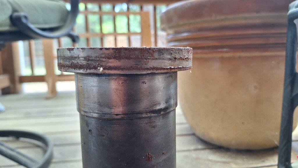
Once the fins are off you should be left with a large metal shaft and two different sets of screws holding metal plates onto the boat.
If this was only a seal replacement, then the inner metal plate with 4 screws would be all that needs to be removed. This is only a thin metal plate that will likely have an RTV Silicone/adhesive keeping it in place and water tight. If this is all you need, both of the double seals have a “V” shape with the channel of the “V” facing towards the water. A wood screw inserted into that area works well to get a solid enough grip to pull it out. Because I am rebuilding mine, it means this and the larger housing it seats on needs to come off.
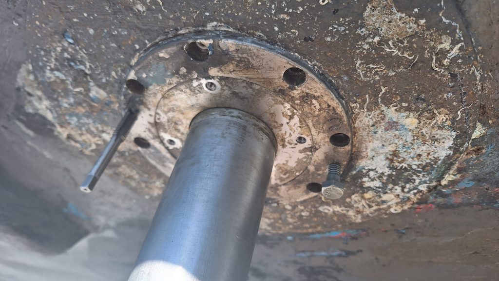
There were 2 (and the replacement I got had 3) screw holes to back this piece off the larger housing. Because its exposed to water and had more RTV silicone/adhesive in the threads, I purchased a cheap harbor freight tap and die set to act as a cleanout tool on the threads and help with adding the backout screws (pictured in use above). This required a lot of back and forth work to get it cleaned and was a bit time consuming, but ultimately worked wonders. Inch and a half or two inch grade-5 bolts from tractor supply did a good job of backing the plate off.
When the RTV seal holding this piece in place finally broke, a stream of brown water came pouring out of the housing. This was expected given the water intrusion inside the boat, but under normal circumstances is a bad sign and is a sign you need to take the guts out and rebuild it.
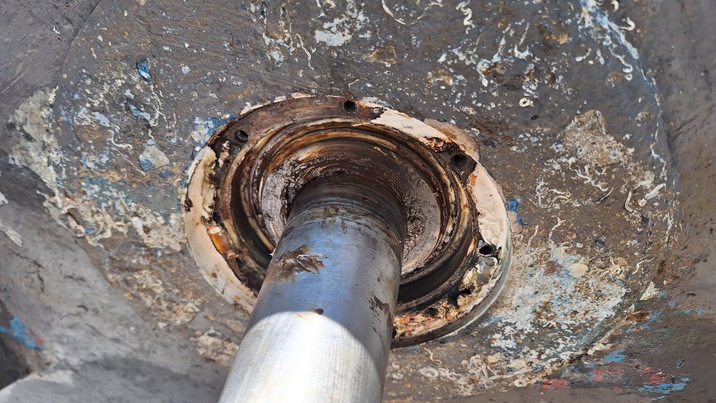
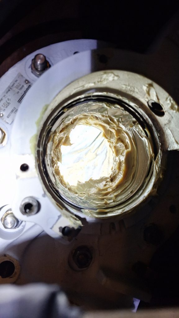
This is supposed to be a white grease that is packed inside the bearings. About a half hour was needed with a fine pick tool pulling out all the old RTV sealant, and then another 20 minutes or so to tap the 8 screw holes as a way to clean them out and remove existing sealant which made its way in the threads during the last install.
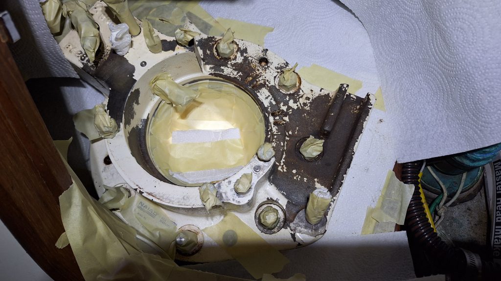
With the fin removed, shaft exposed, and housing plates removed, it was then time to focus on the inside of the boat. This is how things looked when I was ready to begin taking things apart.
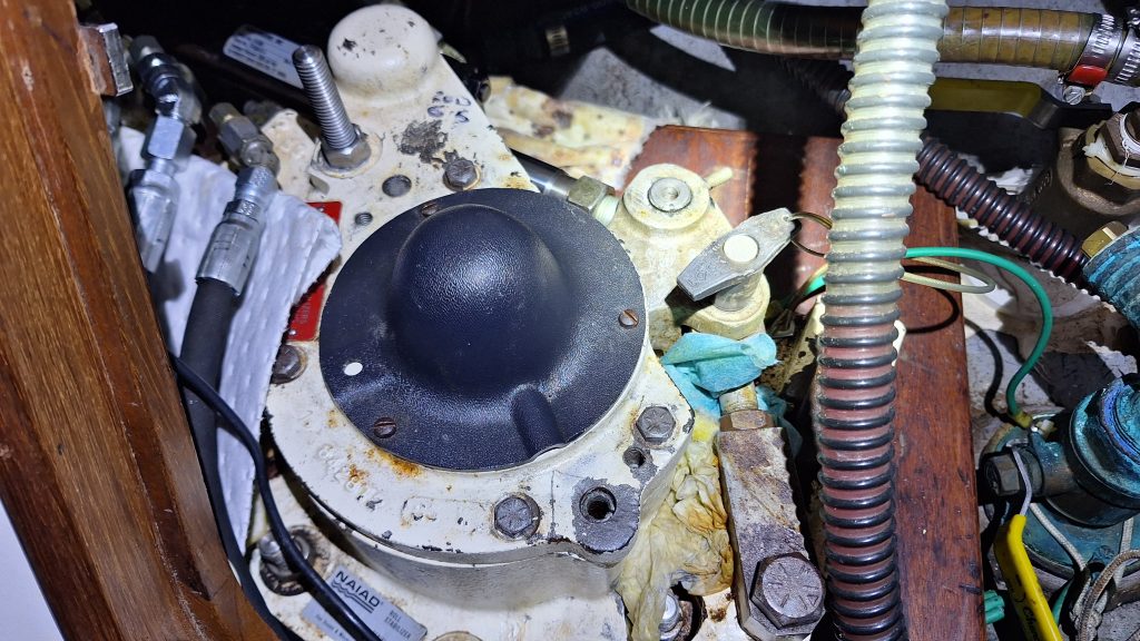
The 201 model has nothing under the black plastic housing, but had this been one of the other models it would have been covering an indicator dial of some kind to show the position of the stabilizer and this would have needed to be marked in position someway. This photo was after it was discovered to be leaking, and after new hydraulic hoses were put on so there is an excess of oil pads and paper towels to try and keep things from dripping everywhere.
What is not as obvious is evidence of the leak from this angle. The way the stabilizer is mounted, the central area holding the shaft is shaped like a letter “C” and the bottom portion of it would pool water that would eventually overflow to the right, where the paper towel is wedged between the locking pin and the main body.
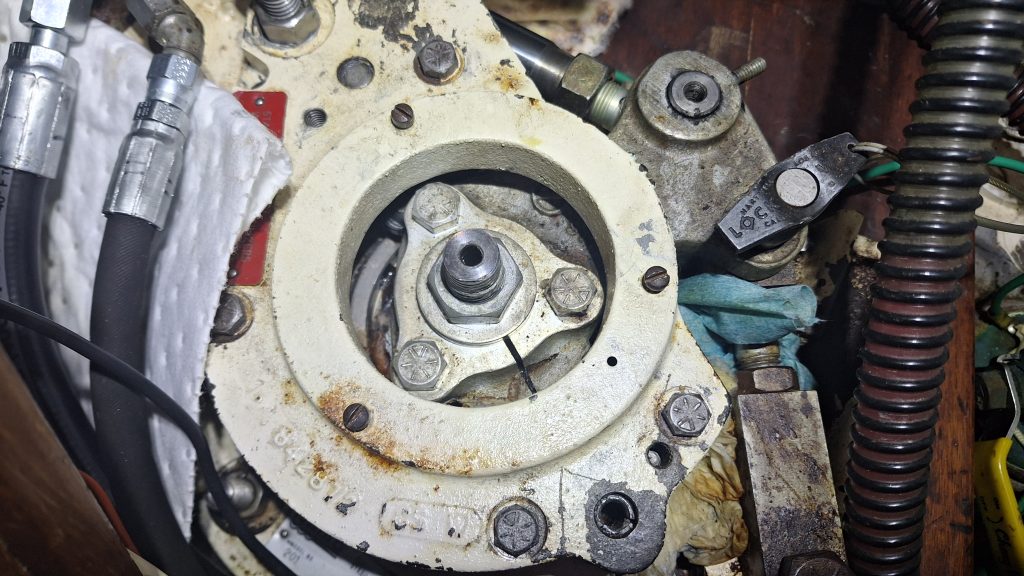
Removing the plastic piece, a leak still may not be noticed to someone unfamiliar with this system. Of the 3 exposed bolts in the center area, you can just start to see a little rust in the bottom left, under the metal plate.
Removing the 4 bolts and one nut holding the top bracket on, it required a couple backout screws to come off completely. With this piece off, it now becomes apparent there is a leak, and why an inspector unfamiliar with the system may have missed it.
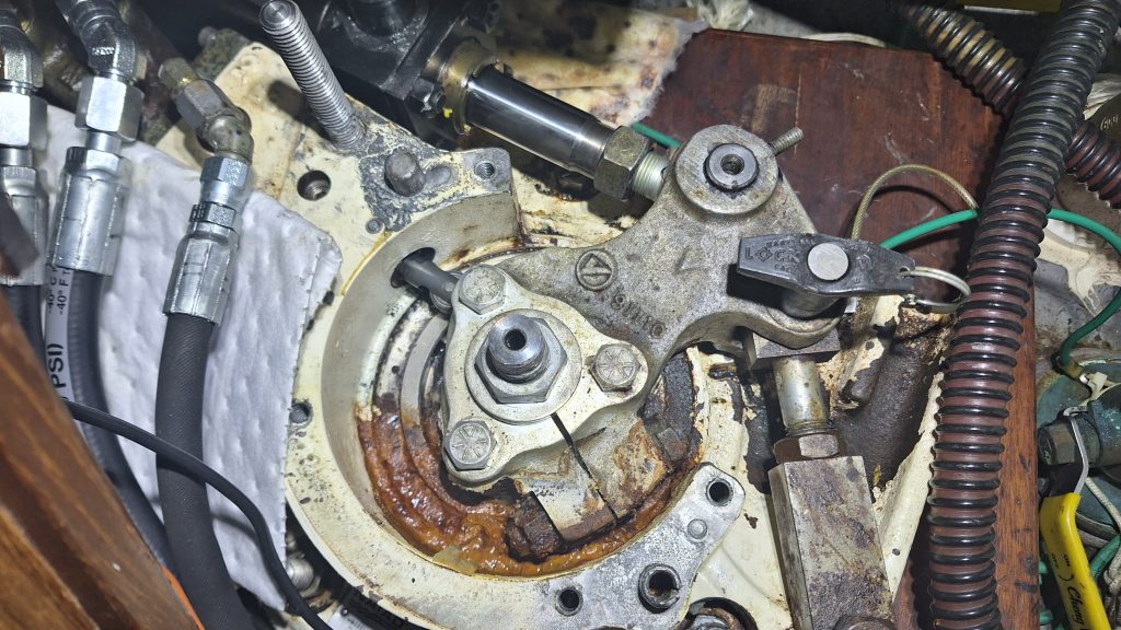
Even if you tried to place your finger in the area of the open channel, the horizontal bolt squeezing on the central shaft would have prevented you from seeing or feeling the rust or water. You would need a small scope type camera, or would need to look at it from an odd angle to see evidence of previous water intrusion.
Lets explain what we are looking at here.
- In the center is a large nut that is on the very top of the pin which sticks out of the water and the fin mounts to using a large bolt on the outside.
- Outward from the center are 3 bolts which hold a large, solid metal housing. The shaft fits inside this housing, and the outside of the housing has two race bearings which allow it and the shaft inside it to rotate freely as one.
- The horizontal bolt and nut to the bottom-right of center squeezes the top of the shaft (which is slotted with teeth for rotational strength) and keeps the pin tightly in place and attached to the piston. This is what prevents the piston from pulling out.
- Top left of center is a manual roller feedback assembly that rides along a flat piece of metal the 3 bolts go through. This tells the system where the piston is located/how much to move.
With the benefit of hindsight, I’d disassemble in the following manner:
Start by removing your locking pin that was keeping the fins centered, and adjusting the position of the piston so the horizontal bolt that squeezes the shaft is accessible and remove it. The other side of the bolt (inside the channel) snugs up to a lip so that you can tighten or remove it from the outside only. This also assumes your locking pin coupling has the nuts bound/locked so that when locked in place the fins are always center, this is important for reassembly later.
Once the bolt is removed (or at least loose because you may not be able to remove it yet) you can now start unscrewing the large bolt in the center that represents the top of the shaft going out. This is now the last bolt holding the shaft in place, so have someone (or something) on the outside of the boat ready to catch. As you loosen the bolt, you should be able to give it a few “love taps” with a hammer to slowly back it out. This large bolt and the washer underneath will prevent it from completely dropping until ready so you can be prepared. This pin which is about to drop out is solid stainless steel and I’d estimate weights at least 30-40ish lbs so make sure what ever is on the other side can carry that weight dropping a small degree.
With the pin out, you can now remove the 3 bolts of the mount which is connected to your piston. Once loose, you can twist and lift the assembly off and out of the way, piston and all. If you have the manual feedback wheel, this is being pushed into the metal piece by a spring, so just hold it back or be mindful of it when removing things around it. It will pull right out if you pull on it, and there is oil behind it from the system, so be aware if you remove it, motor oil will be everywhere.
At this point, you should see a piece of metal in the center of the housing with 3 bolt holes from the bolts you just removed, a backout bolt hole, and a 1.5″-ish hole going to the outside of the boat. The photos below show these pieces after they have been removed from the housing. One is designed to sit on top of the other (lets call it the ‘top-ring’), and so you must back it out with that screw hole to get it off. Not pictured is a seal that goes between the outer rim of this top-ring and the inside channel of the larger housing which is mounted to the boat. Mine also had thin plastic shims between this top-ring and the large metal piece below it. (if you have them, note color and number if possible)
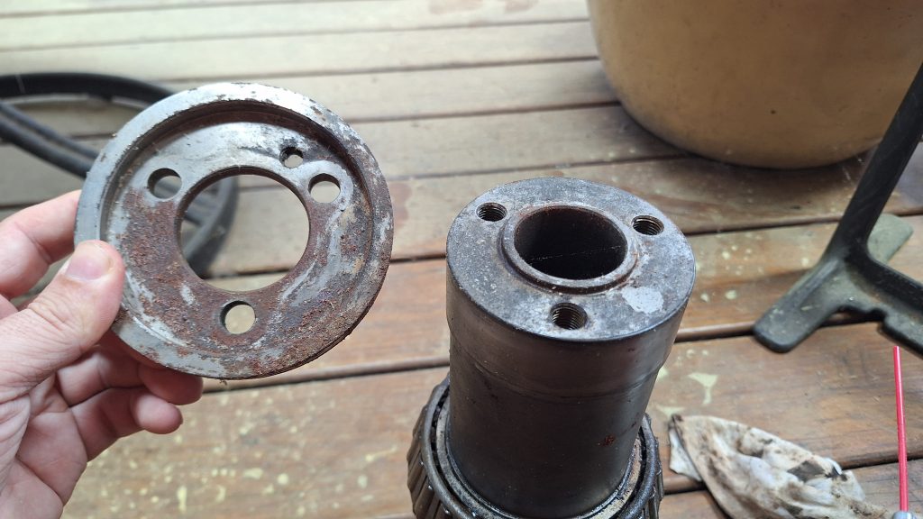
With the top-ring removed, you can likely remove the seal as well which helps keep the grease inside out from the exposed air in the boat. I had a spare, so I was destructive in removing mine. Be aware there is a large, thin, stainless steel spring on the inside lip of that seal. If yours has broken, remove the pieces when removing it, it does not tolerate salt water well.
Once the top-ring is removed, you are now left looking at the inner assembly which formerly held the shaft in its center, and still contains the bearings on its outer diameter fit snugly into the larger housing assembly. Using a block of hard wood (I found hickory to be most effective at holding shape the longest) and a 3-5lb hammer – administer lots of “percussive force” to slowly back it out from the inside of the boat, and pushed to the outside. Hit it directly off the center where the steel is solid, don’t hit the bearing assembly.
It should start slowly separating from the bearing which is only about an inch thick. This is a long, tedious process to back it out. Be patient and hit it evenly and often, its moving fractions of a millimeter at the time. Once free from that top bearing, a person (or something on the outside) will need to catch it. The assembly will still have the outer bearing on the outside half when it falls.
After it falls out, your small hole looking outside the boat should now be a large hole looking outside the boat about 4-5 inches across. There will (hopefully) be lots of grease that was packed between the bearings, start digging it out. Dont get it perfectly clean yet, just get the bulk of it.
For the next step (assuming you are replacing the bearings and races, which if you have water intrusion and made it this far, you should) its time to knock out the races. I first tried to use a long piece of hickory and found in some areas it simply got eaten up and splintered too much to make a difference, and required me to cut it off fresh to get back to a clean edge. Still, it required several cuts and eventually I switched to a large steel pin I had that was more fit for the job. Doing it again, I’d purchase a 1″ thick 12″ long brass rod and use that. I ended up using a metal pin that worked best, but I was purposely being a bit gentle since it was metal banging on metal.
The races are installed in a way where from inside the boat, you knock the outer one loose by hitting it to the outside of the boat, and from outside the boat, you need to knock the inner one loose by hitting it into the boat. Imagining a cross section of the entire assembly, the races are angled in a way where they squeeze together when tightened. Because you are always hitting the far raceway, and need to go through the housing assembly, I recommend a round bar of at least 8-12″ so you have room to swing a hammer. A square bar (or square block of wood as I discovered) will have the corners destroyed as you try and hit the inside of a round object with a 1/4″ lip with a square tool.
Again – These races are on there tight. It took a while of starting at the 12 o-clock position, hitting it once or twice, then sliding it around to the 4, then 8, and then back to 12. Or doing a 12 to 3 to 6 to 9 and back to 12. Each hit moves it ever so slightly. Find a rhythm that works for you, and be patient.
In my case, I had a spare set of everything. In hindsight, I wish I knew the bearings in use and bought just those, and maybe bought only a new ‘top-ring’ (mentioned above) to ensure the outer seal was not as rusty as the one you see above, but the old one would have likely cleaned up fine. The picture earlier was after this was all done and it has been sitting on my deck for a few months.
Below is a picture of the bearing and raceway. All 4 used the same ones.
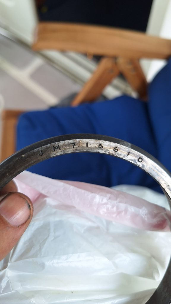
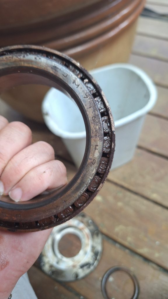
To save someone in the future some time, and a good chunk of money, the bearings and races were Timken JM716649 bearings and Timken JM716610 races. These can be picked up at auto supplies or an online store of your choice, but they are nothing special or unique.
Once the bearings came out, it was time to don an air mask and spray the crap out of everything with brake parts cleaner. The stuff works magic in removing grease, film, and anything you dont want, but it is nasty. Wear rubber (not nitrile, they will be eaten away) gloves and if you wear glasses, put goggles on anyway. The outer coating of my glasses melted from all the fumes. Let the entire thing dry out for a while.
The large metal piece you recently knocked out also has a bearing on the bottom, snug up against a flange. Fair warning – This is going to be a pain to get off. A vice or something that can hold the large metal piece still will be needed. The top of it has a lip and so itll never stay perfectly upright when you put it upside down. Grab a beer, and a good solid surface to place it, and start knocking away, it’ll take a while. I found putting it on a 3/4″ scrap piece of plywood (any soft wood should work so you don’t damage that top lip) and a couple of sandbags to wedge it upright help with two pieces of hard hickory wood sticking out either side for the 2nd half. If you have access to better tools, you may find a better solution.
Regarding that “2nd half” reference – The bottom bearing needs to be knocked out twice, first from the bottom part where it sat against the flange, and then through the top part where its counterpart will later rest. That 2nd part is tricky because the part becomes a bit more unwieldy. For me, having a sand bag that could sort of mold around the shape of it while also keep my piece of hickory in place helped, but overall this was a tedious, time consuming task.
Beautification
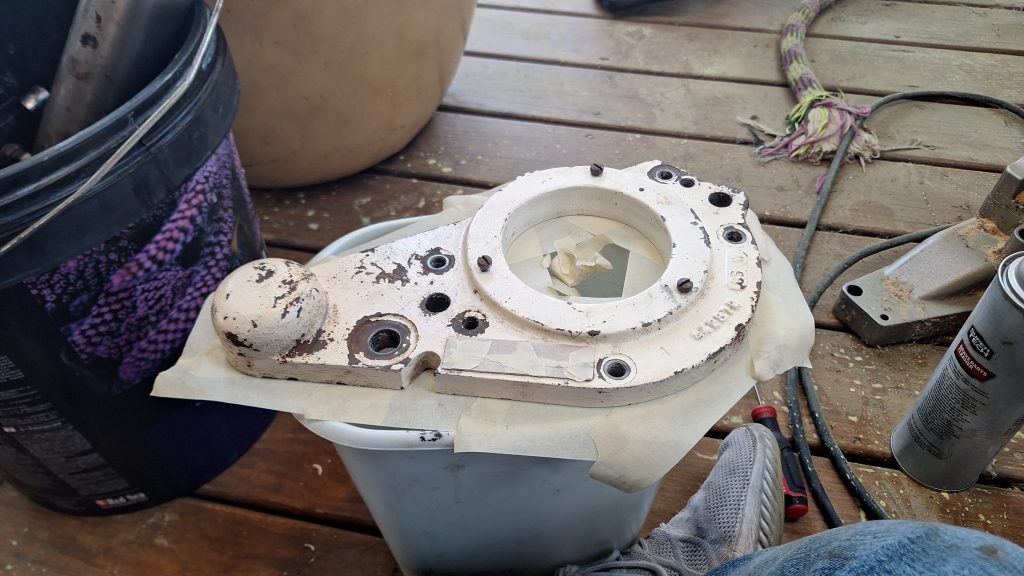
With all the parts out (and later placing an order in for some new shafts I did not plan on replacing) I decided to spend some time making everything look a bit nicer than it was. I hope not to have to disassemble everything to this level again, so now felt like a good time for some paint and cleanup.
Removing the big loose chunks with a wire brush, I applied paint remover to some spots hoping to lift the semi-stubborn areas that were all half rust, half still adhered paint, and showing signs of age and neglect. I could have painted over the old but it looked like in time the layer underneath would flake off, or just show a lot of potmarks from the mix of still adhered paint and rusty areas. It took several coats of paint remover to get the old paint off, and painters tape helped protect the areas that were still well adhered which I planned on painting over.
I am by no means a professional painter, I just needed to get most of it covered up and at least looking better than it was before. I didn’t want to take ALL the old paint off just for the sake of being able to go down to bare metal across the entire part.
A layer of Rustoleum bare metal primer spray paint, followed by a white topcoat finished the process of simply cleaning it up, and getting rid of the old rust that was rampant across the part.
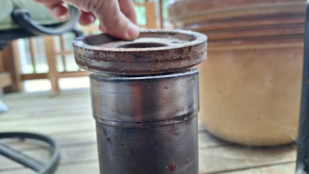
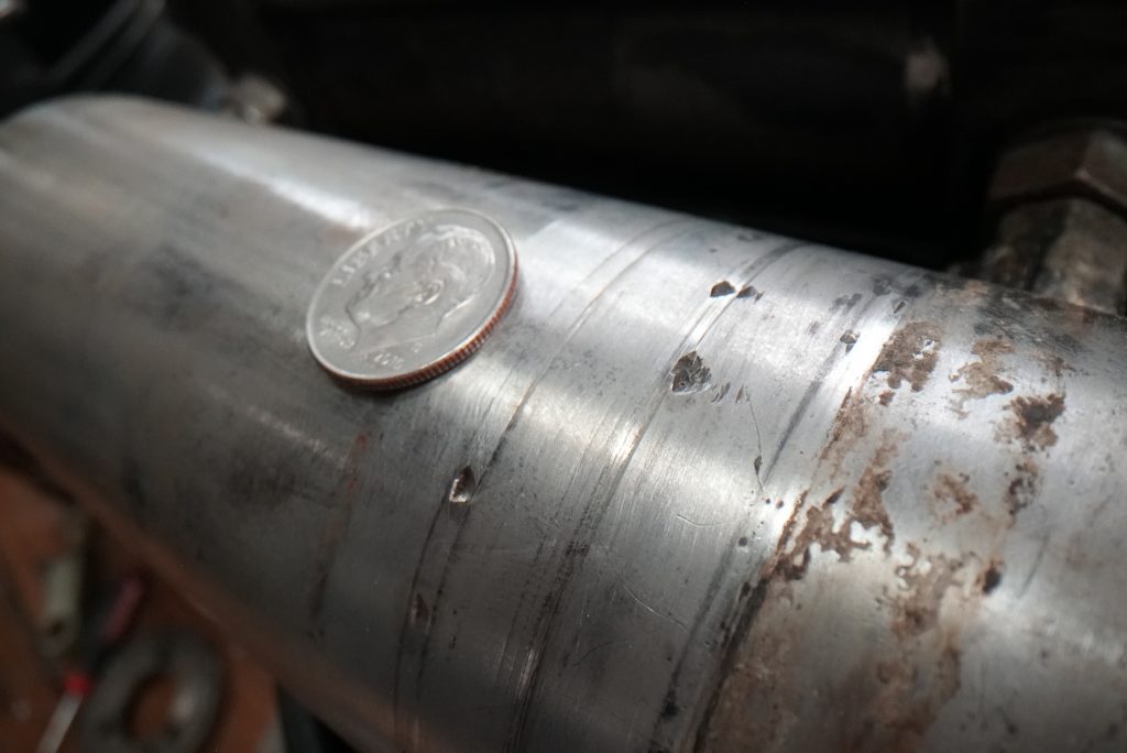
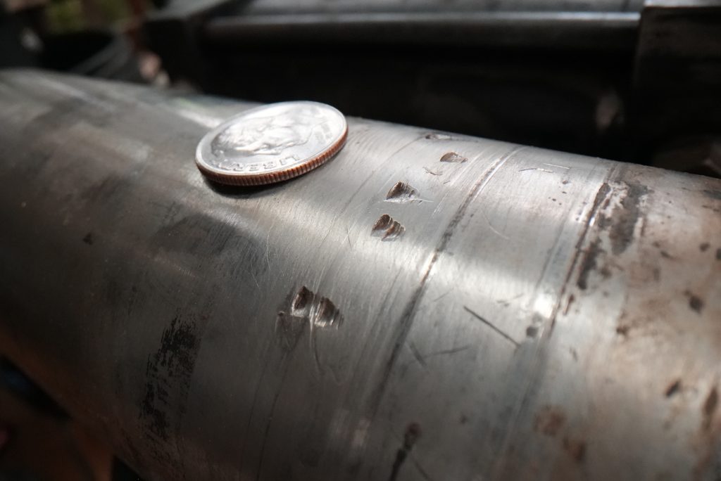
You may be wondering – What about the new shafts I needed order? Turns out the old ones had a mysterious set of dents, as if the bottom part of a threaded bolt was hit against it, which caused an indentation a bit shallower than the width of a dime, and RIGHT on the area where the seals would otherwise be installed.
The photo below shows this, and you can see the wear marks of where the o-rings are to be installed. Simply put, considering the amount money I’d spent on spare parts and my significant time investment up to this point, I was not willing do to this all over again because of a few small nicks. So new shafts it was…
If you have the parts now disassembled, now is the time to get them cleaned up using the cleaners and methods of your choice. Before you know it, it’ll be time for re-assembly.
Assembly
Assembly of this system largely follows the process above but in reverse – shocking I know! If doing this from scratch like I did, make sure the housing is completely clean, and not a spec of dirt or wood from any ‘removal activity’
If you have them, install the races in the same orientation as the old, and use a little grease on the outside to help them slide in. WD-40 works too, just use brake cleaner to clean it up before packing the grease and make sure you have a feeler gauge (or some fingernails) to make sure its firmly seated and flush onto the lip of the housing. I noticed a change in the tone and feel when hammering it in that let me know it was more “solid”, but still gave it a round of taps above and beyond to ensure there was no doubt it was seated.
As for grease, Naiad told me they use Fiske Brothers “Lubriplate Multi-Lube A” to pack everything. Searching for this exact brand and type, you will find many similar styles, but only one “Multi-lube A”. Unfortunately, the smallest amount of this exact type they sell starts in a 5 gallon bucket. I estimate I used less than 3/4 of a gallon across both and still have plenty to spare. On an unrelated note, I am trying to find unique applications to use my remaining 4.5 gallons of white lithium grease.
I would guess that if you can find a water resistant, high temp, extreme pressure white lithium grease, you can use it, but again considering the money I was spending, I was afraid to substitute it for something else given all the work that went into it thus far.
If you have not already, put your new bottom bearing on the large metal housing that is going to hold the shaft. When I assembled mine, I tried putting it in the freezer for a while hoping it would shrink, and left the bearings in the sun to warm them up – it was not enough. I was hoping the temperature differential would cause them to drop right down but that was not the case. More beating and hammer work was required.
The bottom bearing (or, all bearings for that matter) has a metal cage that holds the individual rollers in place. There was no way to drive this piece down without hitting that metal, which would transfer it through the rollers and into the base of the bearing. For that reason, you need to be more gentle, and even still mine was slightly malformed by the end of it to the point where the rollers and this cage came off near the end and I needed to manually put them back together. If you pack the bearing full of grease beforehand, this will help hold them in place should the cage come off, but it also makes overall handling more difficult. I did one dry with no packed grease, one with packed grease, cant say one felt easier than the other, they both had their unique challenges.
If you have never packed a bearing before, I don’t know how to describe it in writing other than you need to find a way to use your hands to squeeze grease in between each and every individual roller. I would call it a funnel/compression type motion that needs to be repeated in the same spot, moving the grease inwards little by little. Do not just give the rollers a dusting on the outside, its got to be really in there and completely surround each individual roller.
Should the cage come off and allow your rollers to come loose, take note that there is a slight taper one way in each roller. Its much easier to see when the bearing is dry. Once its packed with grease this is very difficult to tell, but will cause it not to seat properly and the cage wont go back on (don’t ask me know I know).
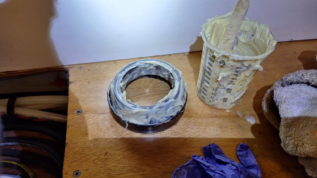
In the housing assembly thats on the boat, your races should be in place, so start packing grease along the inside. Big thing is getting some of it in there to start. You will add more later. Fair warning, the stuff gets everywhere.
I dont have many photos since the sunlight from the outside caused my cameras ISO to go haywire, but the above photo shows the initial packing we did. In hindsight, do less to start, and add once the large cylindrical center piece is in.
Speaking of which…
The next step was in my book the hardest part to work out, but ultimately I think I found a reliable method.
What is about to happen: The large cylindrical piece of metal, the one with the roller bearing you just installed down to the bottom flange, that needs to be inserted from outside the boat inwards, while simultaneously having the top roller hammered down while it is being held up. Don’t bother trying to have someone hold it while you hammer it, that won’t work. Here is what I found.
You will need to buy the following:
- a 12″ long, 3/4″ thick threaded rod.
- 3 bolts for above rod.
- A set of washers that stack smallest to largest to give your last washer the largest surface area possible. buy 2x of each.
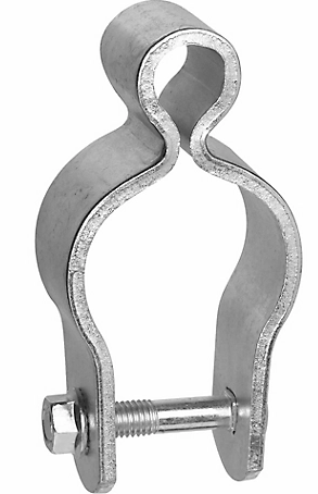
- A pipe gate hinge (or similar piece of metal that can withstand a lot of compression force through the center)
All of these things I was able to pick up from a tractor supply for <$50 total. This is going to let you build a simple device to hold the large chunk of metal with your bearing in place, while hammering the 2nd one down and getting it snug.
You will also need the round top-ring that has 3 bolt holes and the 1 backout screw hole. I’ll continue to reference it as the ‘top-ring’ here.
On one end of the rod, thread 2 of the 3 nuts to the far end and bind them (twist one against the other so they dont move) or get someone to keep a wrench on the outside. On top of these stack your washers. put the threaded rod through the larger opening of the pipe gate hinge (picture below) and then put the rod through the hole the stabilizer shaft will go through on the large cylinder.
One side of that hinge should be touching your washers, the other is on the lipped side of the metal cylinder you are about to put into the open hole of the stabilizer. This is going to take the load from the threaded rod and push against the bottom of this lip.
With one person inside the boat, and the other outside with this assembly, feed the assembly with threaded rod through the opening and have them keep it pressed in place. VERY IMPORTANT – This is now the time to finish packing the area between the two bearings with grease. Put as much as you can fit including the area the inside roller bearing will go. Excess will squeeze out the rollers.
Once greased, the person inside the boat then needs to put the inside roller bearing in place, place the ‘top-ring’ on top of it (flat side on the bearing) followed by the other half of the washers you bought, then the 3/4″ nut and get it hand tight. The person on the outside needs to keep pressure up as to not have your grease get squeezed out.
Getting this started is the hardest part. Grease is likely everywhere and making things difficult to handle. The bearing doesnt want to seat perfectly flush, and tends to angle to one side or the other. Using a wrench on the nut/threaded rod to get things a only a little tight, maneuver things in a way where the top-ring is evenly spaced around and on top of the inner part of the roller bearing.
With two hands, one on a hammer, the other on a wrench, tighten the bolt while hitting evenly around this metal top-ring to have it transfer to the bearing and get it seated. I can speak from experience, it will try and go sideways on you, binding up and being a pain. But once you get the first 1/8th of an inch on and seated, it will all be downhill from there. Turn the nut until tight, bump with a hammer, and turn the nut again until tight. You will feel it easier to turn after every hammer strike. Continue this until its fully seated and snug into the housing assembly. You will find it no longer wants to move as you tighten.
There is a very small gap between the ‘top piece’ and the inner metal cylinder that makes it squeeze between the bearings before it gets perfectly flush with that top piece. Make sure there is NO PLAY in any of this. It should be solid. Otherwise flip the top-ring around so the flat side is facing the inside of the boat and the outer lip presses against the bearing. Use the threaded rod approach to suck it up more until tight and use washers to keep the load as far to the edge and away from the center of this piece so you don’t bend/break it.
Once this is complete, the threaded rod assembly can be removed. Both of the roller bearings should be tight and there should be no play in the system. The inner seal housing will need to be added (with the channel facing the grease so the inside of the boat sees the flat part) and can be gently tapped into place using a block of wood to spread out each blow.
Before you add the top-ring back where it should be, if you have any shims, now is the time to add them. They are literally paper thin, and I used a straight edge to add/remove them in a way where everything felt level level. The top-ring then fits snugly in the inner seal you added in the paragraph above.
Get your grade 8 bolt through the piston arm horizontal locking mechanism, and all your existing bolts and nuts handy. the next steps go quick and are all done fairly quickly.
At this point – The internals are set, now its time to feed the shaft in from outside. Feed it up as high as it will go and adjust the piston arm so it goes through the teeth of the top of the shaft. If your system has the roller wheel for feedback, maneuver that as part of adding the piston arm back. The large washer and screw at the very top of the shaft will hold things in place until you are ready to tighten things down.
From here, torque the 3 bolts to secure it all in place and tighten the nut at the top of the shaft followed by the horizontal one, and then give the pin a good push/pull from the outside to further ensure all parts are solid and there is no play or slop what so ever. Once confirmed, add the top half of the housing plate that keeps everything in place, and torque it down to spec. Add your locking pin to put everything back in the “center” position. The inside should be complete, time to move outside.
Depending on how well you packed the grease, some may be coming out. Mush it around to be flat and completely cover the roller bearings. You can fit a good bit in there, but dont let it build to the point it will squeeze out from the larger plate since it may ruin the seal you need to make using the RTV silicone/adhesive. I found it best to have the backout screws already set in the outer plate, and did a dry fit to make sure no grease stuck to the backside of the plate and it would make a good gasket seal with the boat once tightened. Even with a dry fit thats hardly torqued down, you will need the screws to take the piece off.
If you have not already, clean up any and all of the old RTV silicone/adhesive that was there before. Get the surface as clean as possible by liberal amounts of brake cleaner, but be careful not to let it get on the grease inside the housing. I used a pick to dig it out of tighter spots.
Unrelated to boats – If you want to make a good seal with something like silicone or caulk, I found it best to hold the tube at a 45 degree angle away from the direction you are looking to apply and squeeze so it pushes into the area, and not just skims the surface and goes with it. So, imagine you are filling an area and moving from right, to left. I hold the tube so the bottom is to the right, and then I move to the left, keeping it angled so the area I am moving into has an obtuse angle. That forces the caulk (or what ever it is) down into grooves below and I have found creates a better seal.
It took about 3/4 of one of those automotive squeeze tubes per stabilizer, so buy at least 2. There was a substantial gap in some areas that needed to be filled, and the first time I tried to apply it wasn’t enough, I got no squeeze out and had to back the plate off and add more until I was satisfied the amount of squeeze out I saw confirmed I had full contact with all parts, ensuring a waterproof seal. Torque the 8 bolts to spec.
One observation I had, on Valkyrie the size of the lip of this larger plate was different on either side of the boat (say 3/8″ on one side vs 1/2″ on the other?) At first we thought we installed it wrong, but now think it one was installed just slightly higher in the hull, causing it to be installed across a larger bow in the hull, but was otherwise tight. So don’t rely on eyeballs alone for this one.
With the larger plate installed, you are ready for the double seals to keep out the water. My Naiad documentation recommended a combination of RTV silicone grease on the outer edge of each seal, and waterproof grease on the inner edge. Feed it mostly up the shaft, then add that stuff, else you end up wearing it trying to keep them separate. Once in place, the smaller plate with 4 screws goes on.
Clean up any remaining RTV silicone off the exposed metal and maybe add a bit of bottom paint primer when its a bit tacky if you are looking to paint over it later. Its a lot easier now than once the fin is back on.
Speaking of, liberally spray the inside of the fin and the stabilizer pin with brake cleaner. Get things squeaky clean. No grease or residue should be on either. The bolt holding the fin doesnt get much bite, maybe an inch or so? This means when you add the fin on the piston, someone needs to hold it snug while the other person tries to get the pin in place and screwed in. Remember, the raised part of the washer faces the hex head. I also needed to add a paper towel stuffed inside my socket to ensure the pin was close enough to the edge to get a bite of the threads, otherwise it was too shallow.
Get it hand tight (or just over) so that the fin stays in place on its own but can still be forced to a new position. The pin inside the boat should be locked, so now its time to center them before torquing it up for good. I found it a LOT easier to eyeball center from the back of the boat, where the tapered edge of the fins acted like a “center” line, and I could easily tell if they were slightly angled up or down. From the front of the boat you really cant tell because its more rounded and you cant see the back half of the fin. Given the low speeds of the Nordhavn, I don’t think it being off an inch or two is really going to have that big of an effect while underway, but looking at it from the back I was confident we got it.
Once in place – A 2×4 wedged between the ground and fin provided the resistance needed to ensure the tightening of the bolt didn’t move the fins from their centered position. I opted for 300 ft-lbs instead of loc-tite & 250 since the large bar I had made the extra 50 lbs fairly trivial.
Finally, go in front and behind the boat to check your work and maker sure it all looks good, and bask in the glory of the money you saved for a job well done!
Lessons Learned
Knowing what I know now, I would be willing and confident I could rebuild the stabilizers again from a skills and mechanical perspective (hopefully I don’t need to any time soon). It was a daunting prospect at first but taking lots of pictures along the way and documenting my disassembly steps on paper made things fairly straightforward.
Some things I learned (summarized from above) to hopefully help anyone looking at a similar task for themselves in the future.
- This is a 2 person job, and physical strength is required. Most of it can be done solo, but there are a few key steps that need two people, and some metal parts are heavy to handle and hold in place for minutes at a time.
- Naiad was able to send me all stabilizer parts (to the USA) using standard ground shipping very quickly. I could call, pay, and get the parts a few days later. None of them needed a lead time.
- Amazon sells a 600 ft-lb torque wrench that is about 3 feet long. I highly recommend it, as it will made removal and adding of the fins a breeze. A 12″ extension was also needed.
- I went through about a case of brake cleaner fluid. Plan appropriate safety gear working with that, you dont want it on your skin. Rubber gloves work well to protect you, nitrile don’t and will melt.
- If you have water intrusion, take everything apart first to find what you can salvage, avoid pre-ordering unless you are really in a rush I would not skimp on bearings. I’d buy Temkin bearings direct (not through Naiad). Take the old off to find if your model is different. Remember its 2 part #s, a roller bearing and a raceway.
- Buy a tap and die set as well to help with cleaning up all the gunk and marine life out of the exposed threads or those covered in RTV silicone adhesive.
- Bring tools (Saw, screw gun, and/or general carpentry) to build something to handle the raising/lowering of the fins. They are heavy, too heavy for 1 person to hold and also handle wrenches and such.
- (Water intrusion only) The hardest part is getting the round cylinder in place and on the 2nd upper bearing while also seating it in the housing assembly. Plan on getting creative with how to hold it there (see my threaded rod notes above).
- Buy a new set of stainless screws and bolts for the outside, its much easier to just swap them to new rather than trying to clean up and old screw you know is only worth $0.50 and you are likely to drop anyway.