
Right before I was supposed to be splashed back into the water (and would have otherwise wrapped up an extra-long and painful haul out period) I discovered a bilge full of ATF fluid. Turns out, while the yard I hired to replace the dripless was removing/installing the prop shaft on the wing engine, the work damaged/bent the seal that keeps the transmission fluid in place. Turns out this is not uncommon for older seals that tend to get less flexible with age, if you move it too much, it wont go back to where it was and needs to be replaced.
For me this meant the haulout period would need to continue, and I would now need to replace some shaft seals.
Contents
What You Will Need
For this one, you will need some common, and perhaps some uncommon tools.
- A good tool/socket set (not just for this job, but any boat work really)
- Razor blades for cleaning up edges and smooth surfaces (Flat-tip screwdrivers too for this purpose)
- Spanner wrenches (one that fits 1-1/4″ to 3″ should work, and a cheater bar)
- A gear puller
- Permatex Gasket maker
- Either a ZF seal part kit specific for your model, or the individual seals you plan to replace
- Exact parts I used or really need discussed at the end.
The ZF Transmission
This is not designed to be a comprehensive or official guide, this is simply capturing what I did, in the hopes someone with the same or a similar model can learn from it.
Valkyrie has a Beta Marine BV1505 wing engine that is coupled to a ZF 15 MIV marine transmission. Various google searches suggest it also seems this transmission can be referred to as a Hurth HBW 150 V. The “15” and “150” refer to the output shaft being 15 degrees from parallel with the engine input shaft. There are several similar transmission models which will likely follow a similar process and use similar (if not the same) parts, listed below:
- ZF 3 M (HBW 35)
- ZF 5 M (HBW 50)
- ZF 10 M (HBW 100)
- ZF 15 M (HBW 150)
- ZF 15 MA (HBW 150 A)
- ZF 25 M (HBW 250)
- ZF 25 MA
- ZF 30 M
Replacing the seals which keep the ATF fluid in is unfortunately a bit more involved than a normal seal replacement in something like a car (where you can just pull it from the face you are looking to replace). In this model you will need to split the transmission in half long ways in order to gain access to the assembly where the seals are kept.
A seal replacement kit is sold online for several hundred dollars, which I ordered but in my experience may not be entirely needed in its full capacity. I found the lower seals and o-rings to be required, but the gaskets and other seals to be optional. I half expected the original gaskets to fall apart but mine were still good, but I opted to replace them anyway. So if you are on a budget, you may be able to save a few bucks by ordering the parts I found throughout this post.
Disassembling The Transmission
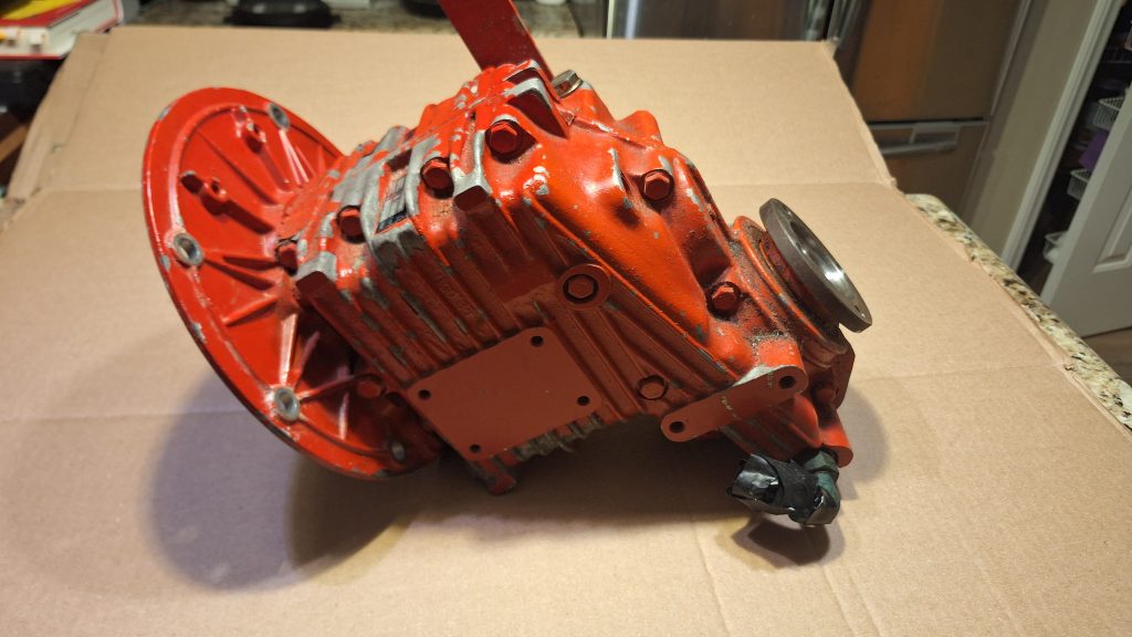
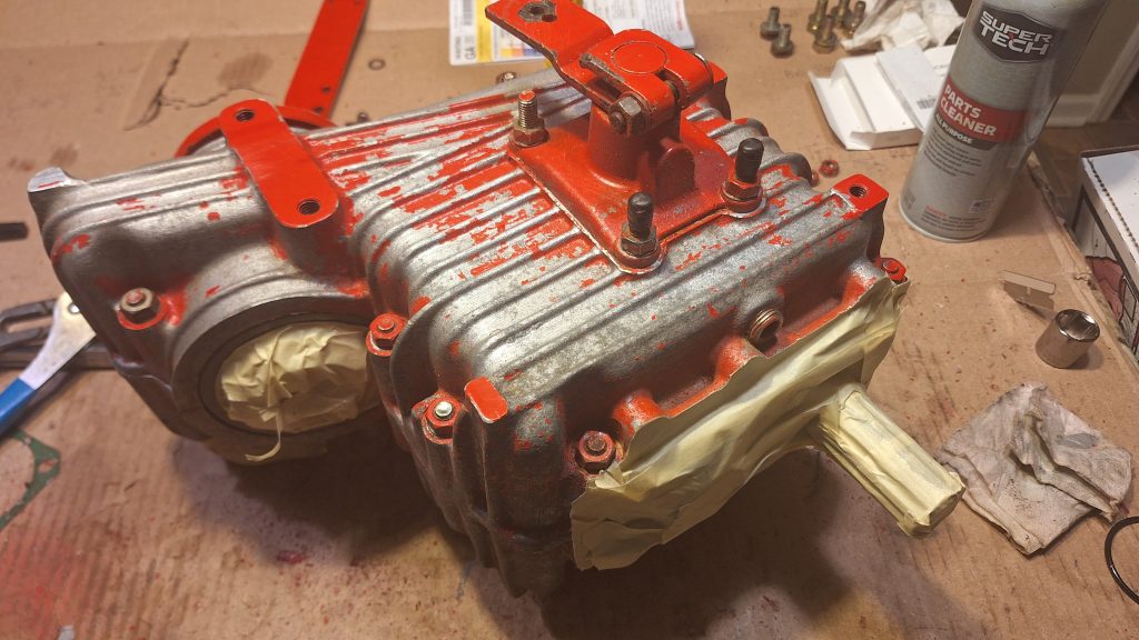
As shown in my photos, start by removing the transmission from the engine and getting it on a large flat workspace. I like cardboard or paper because as I handle things or take pieces off, I can draw directly on the paper or cardboard and circle the piece in question, and maybe include little notes of where it was or anything I deem important.
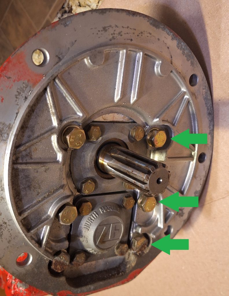
6 bolts keep the housing on the transmission. The 3 arrows below show the one side of the 6 that I am referring to. Its not until this housing is off that the 8 smaller bolts in the 2 groups of 4 can be removed.
Once the housing is off the two plates and their bolts can also be removed. A razor blade will help with removing the existing seal (if you intend to save it) without risking damage to it.
Before you start the next step, turn the transmission upright and adjust your shifter to the neutral position. I learned it will not shift if not standing upright. try and keep it in neutral over the next steps, but if it does kick out, before you remove the last bolt, flip it back to neutral. The official ZF instructions want it to be in neutral during disassembly/reassembly.
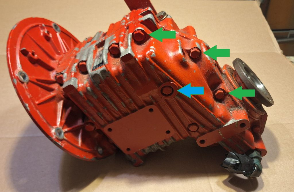
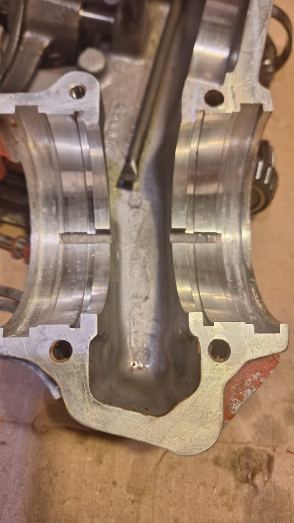
Now the tricky part – Splitting the case. There are several bolts about 3-4 inches long that go through the outer rim of the housing and are secured by a nut on the other side, a select few are noted by a green arrow in the image below. The blue arrow shows one of the bolts that has no nut, My model had 14 total, and 3 with no corresponding nut on the peer half, so make sure you are removing everything from the bolt side. These may be a bit “stuck” resulting from the gasket sealer keeping them glued in, but a bolt reversed through the opposite half will push it through just fine.
When your last bolt is removed – only a little bit of force is needed to split the halves. I used my snap ring pliers between two lips that easily forced the two halves apart.
As you lift it out, you will feel the gears moving and de-meshing, but in my experience each half will keep at least one gear assembly. Handle it gently because there is not much holding them in place, and lay both pieces with the gears up. I took pictures to capture what order things were in, in the unlikely event they came apart unexpectedly.
The video below shows evidence of the bad seal, where the shaft was easily moved by my fingers, and remained that way with a gap clearly visible into the bearing.
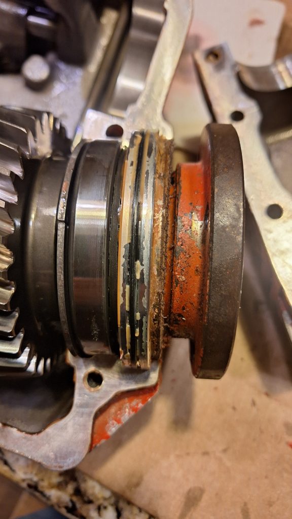
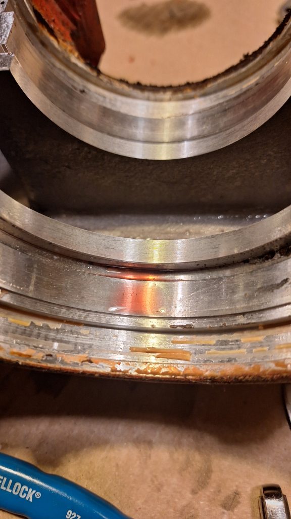
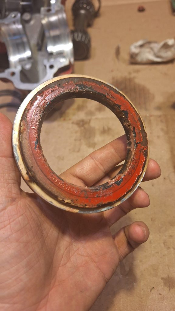
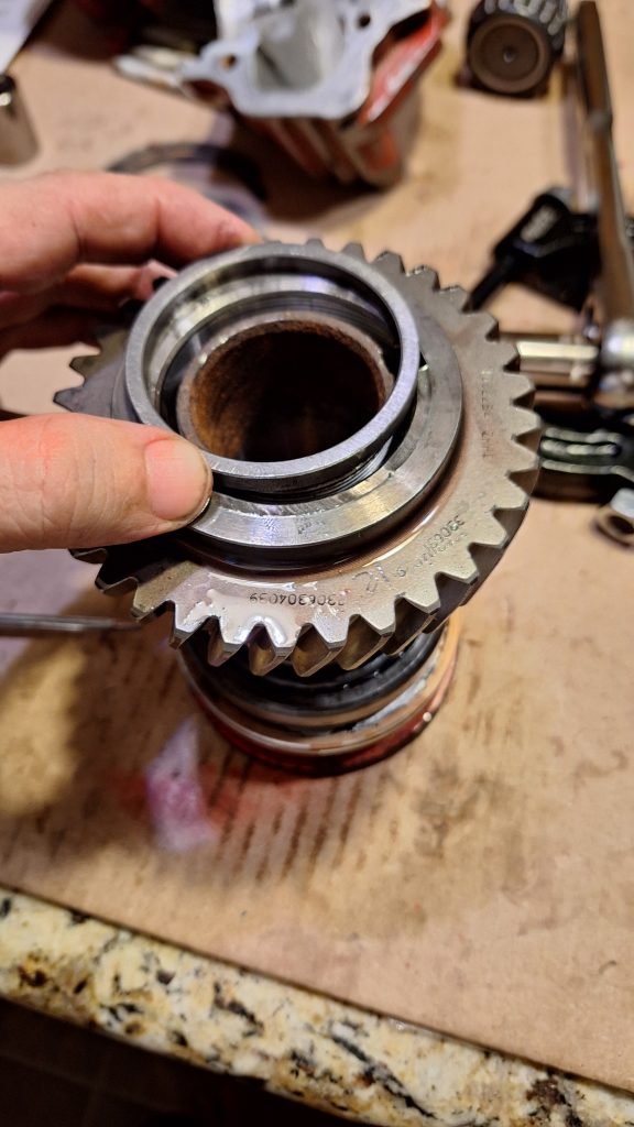
Focusing on the half that has the “quill”, which is the hollow metal flange piece which will hold your prop shaft through its center, give it some gentle “love taps” to coax it out of its housing. As seen in the photo below, mine had a hard, glue like adhesive/gasket material that was very brittle and was mixed on both sides of the metal housing and inside the black o-ring.
Also, when you take it out, expect 4 half-circle shims to come out with it. Mine were two different thicknesses, so take note of which ones go on which side. You can see immediately to the right of the large gear on the photo below two of these halves coming together to form a full circle. These 4 shims are what hold the races tight against the roller bearing.
Once the quill assembly is out, I cleaned up the channels using a flat tip screw driver. The old material flakes and chips everywhere, so wear eye protection. I also used it to clean out some of the bolt holes that hold the halves together for later. A razor blade was used on any and all flat surfaces it could reach to clean them as well.
The photo above shows one of the channels before I cleaned it, and the photo below is after cleaning, having chipped away all of the old sealant and spraying it with parts cleaner to get all the little chipped pieces out. NOTE – The seals are nitrile, and break/parts cleaner will melt nitrile gloves, so id be extra cautious around not getting any of it on a seal.
Cleaning up the channels on both sides of the transmission half, and along the edges of the transmission itself was fairly simple with a clean razor blade. Each half has a very thin film that can be only mildly scuffed up to get the loose stuff off.
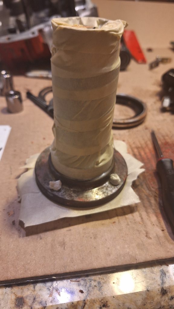
With the “quill” assembly out, now its time to focus on the seals themselves. Unfortunately, because one end of the quill is flared out, it means full disassembly is required to get to both. Everything must be taken off of it off the top so you can eventually get to the seal on the far end on the flare.
Starting at the top, the first seal is a breeze. Just pop it right off.
One thing to note – This is 2 pieces. An aluminum ring, and the seal housing itself pressed inside of it. Placing some blocks of wood on a flat surface, and balancing the thin aluminum piece on this wood allows you to take a flat tip screw driver to the back of the seal and “love tap” it out of place. The seal kit I purchased has the seals, but not this ring. This is unfortunate because cleaning up this aluminum piece is going to take up a significant portion of your time.
The top of the quill has a fine threaded nut with 4 square slots that will require a spanner wrench and breaker bar to remove. It is on there tight. I found it best to drill a pair of holes in a scrap piece of wood, and using two bolts to go through the wood, and into the flange itself, bolt it to the wood. This piece of wood then becomes much easier to put in a clamp or screw into my work table so I could get some leverage on that nut.
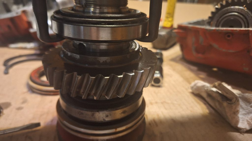
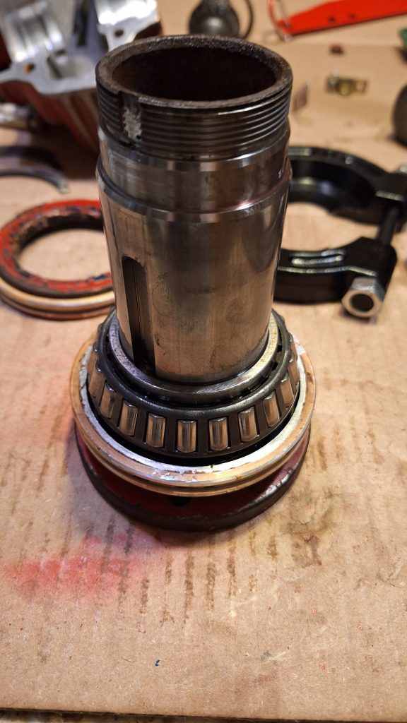
A thick metal spacer is pressed onto the quill, and below it is your first roller bearing. A gear puller pulling on the race of the bearing will pull the bearing, and this spacer with it, seen below. Because you are pulling both at the same time, expect it to take some force, and maybe offer some love taps. If you have not already, take a photo of what direction your gear teeth are aligned. You don’t want to install the gear backwards during reassembly, and then be forced to read overly complex disassembly guide again.
A smaller, thinner spacer is located on both sides of the large gear. Fortunately, its loose and easily removed by hand.
The same puller can be put around a full tooth of the gear and it can be pulled out as well. Once out, you can remove the square key that kept it in place and will need to be removed prior to the last bearing. The photo below also shows the other smaller/thinner spacer from the other side of the gear.
Now is at one of the more challenging parts of the disassembly. The old seal prevented my puller from getting between it, and the bottom part of the roller bearing. The hooks at first pulled on the metal cage keeping the rollers in place, and I needed to hammer it back into place to prevent it from damaging the raceway during re-install. I also didn’t want to use the old seal and aluminum piece for fear of bending the aluminum, but ended up giving it a (successful) try after exhausting my other options.
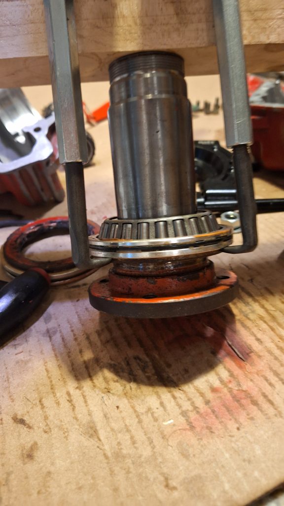
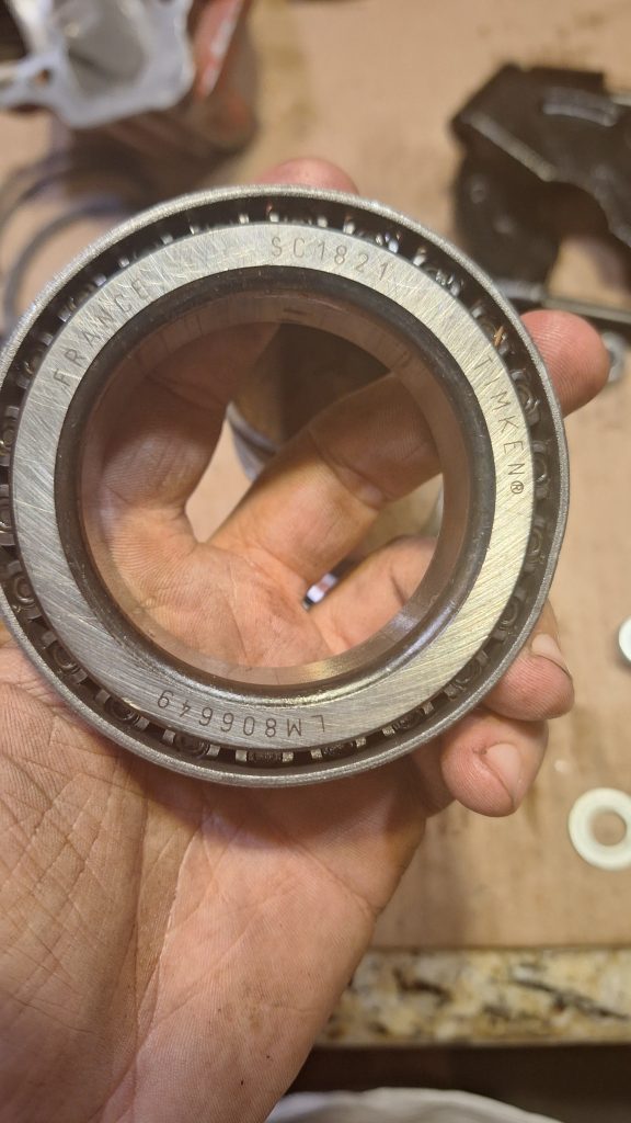
There was a long way to go, so the moment I got it up enough to get the puller feet directly under the roller bearing, I switched to that and pulled it off. In the event you ever need new roller bearings, or a raceway, the roller bearing is a TIMKEN SC1821 / LM806649 and the race is LM806610
With the disassembly complete, I gave the quill a good scrub with a wire brush to take all the old paint off and gave it a touch up, since I don’t plan on doing this again any time soon, and do like having the look of a clean engine.
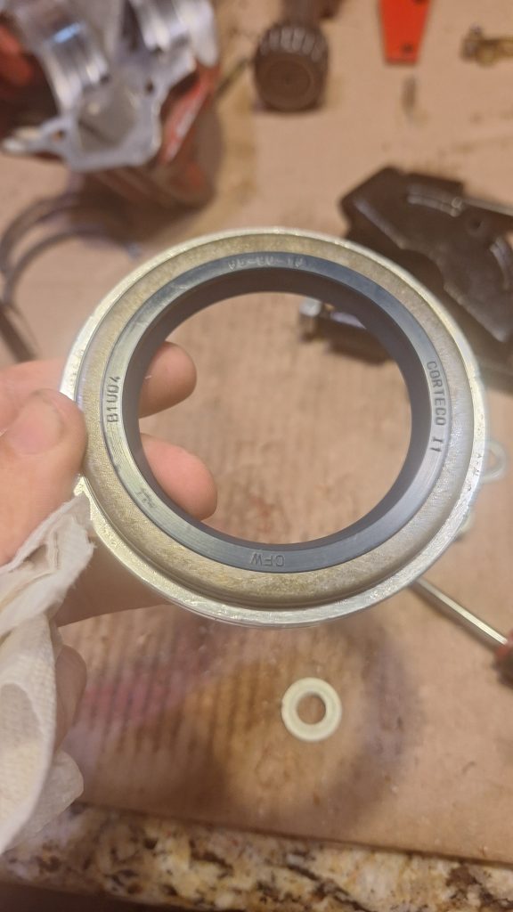
The seals (if you are looking to order your own) are Corteco 65-90-10 / B1UD4. There is an o-ring that goes around the aluminum piece as well that is worth measuring out and replacing but in a pinch you may be able to just slather it with a gasket maker.
Reassembly
To reassemble, simply read every paragraph from this point up, backwards.
On a more serious note – a few quick observations on reassembly. I don’t have a lot of photos here because most of the time my hands were full with parts and I could not easily take a photo. It also would have been a lot of the same photos, but just in reverse. So here are some thoughts based on my experience/
I used a block of wood to tap everything down until it seated tight and as far down as it could go on the quill, obviously doing it all in reverse order. You can easily tell the difference in the “thud” when its moving a bit each time, vs. a harder “thud” when its bottomed out and will not go any further.
I also originally took a photo of the central gear looking only at the diagonal angle of the teeth, this was not the best way. In addition to their diagonal direction, the teeth also have an individual taper to them that makes it where the gear can be installed upside down despite the diagonal direction lining up, and it will not allow the assembly to fit into the case.
I recommend before installing the gear, using your fingers to hold it, lay it on top of the piece it will otherwise mate to and move it as needed so the teeth fit snugly. You will see it wants to “square up” at an angle, where the teeth fully mesh with each other. From there I could see if this angle matched that of the output shaft or not. If you flip it around, it should be obvious which way it goes, so just translate that direction to your quill. Worst case, you pull it off and flip it around like I did.
I also cannot understate – Do a dry fit before anything else, and make sure you know how this will go back together. When I took mine apart, the shims that keep the roller bearing race flush with the roller bearings was at 90 degrees to how the transmission split. I tried to get the same direction for nearly an hour before thinking “Screw it, once its together, it really shouldn’t matter as long as they are flat against the flange” – and thats what I did.
Holding the entire assembly, while also holding the race on both sides tight against the bearings so that everything slid into place was tricky – so I strongly recommend practice before putting gasket maker everywhere.
When you are ready for the gasket maker, make sure it goes on all the flat surfaces of the two halves – a thin line will do given it will be smushed out. In hindsight, I should have gotten the internal surfaces that get bolted from the center to ensure the ATF didnt leak into the bolt holes, and made a circle around all bolt holes for the same reason – but worst case it will cause a very slow leak if any. Be a bit more liberal around the aluminum housing that holds the large gasket you just replaced, it has a lot more play than the two halves that make up the transmission housing.
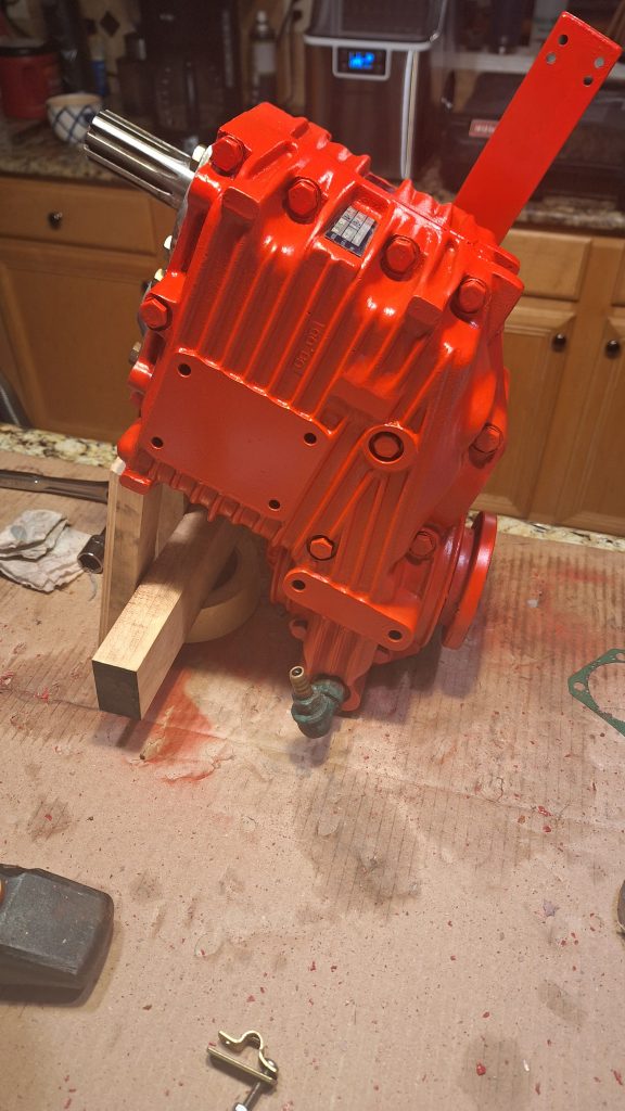
Once re-assembled, I also took a wire brush to mine purely to get all the old paint off and clean it up for cosmetic reasons. The brushing was tedious, and I learned after the fact that taking it outside, and blasting it with air from my air compressor at the max PSI did a much better, and easier job of taking off most of the loose stuff. The wire brush gets paint flecks everywhere, as will the air compressor strategy. Plan accordingly.
After painting with a can of red engine enamel – not perfect up close, but looks good from afar or even a few feet away, and the metal casting wasn’t perfect to begin with, so works for me! The photo below was how I left it with about half a quart of ATF overnight to confirm it didnt leak out the seal (I had no way of plugging the drain hose at the time, so I filled it to just under overflow.
Additional Lessons Learned
Beyond the various gotchas mentioned above – Overall if I had to do this again, I would. It’s not an overly difficult process, but rather just time consuming and tedious. Time will tell if the fix truly holds or if I will end up regretting that statement, but I do not think this is something a single, somewhat mechanically inclined, person could not take on.
I ordered a “seal kit” – Part number 3306 199 004 from a transmission shop for a whopping $450 – and in hindsight if I had more time to disassemble, assess, order, and re-assemble, I would have ordered fewer parts. In this instance though, I wanted to have everything I would have needed to not waste time and get things back together as quickly as possible to save on yard fees. Seals alone looked like they ran around $50 each so the cost savings would not have been much ordering individually. My loss – your gain I hope.
For this fix – the parts I needed specifically were:
– 2x of the output shaft O-ring: P/N 0634 303 690
– 2x of the output shaft seal: P/N 0634 300 146
– 1x of the output shaft inner O-ring: PN 0634 306 072 (one of those super easy to do when there deals)
– 2x of the gaskets for behind the covers that go across both case halves: P/N 3306 301 014
The kit also contains a seal for the input shaft to the engine, (which given there is no chance of play, its less likely for this to fail, but if you want to replace it, its one of those “it wont hurt, and its a lot easier while I’m here” parts – P/N 0634 301 833) some rings for the oil fill and drain that I didn’t use, and a gasket for the shifting cover that didn’t need to come apart for this, so I didn’t touch it. There was also some small springs that were not in the listing on the manufacturer diagrams for this piece, so that could have been just a shipping mistake? Either way these will get filed away under spares.
Total time for disassembly, fooling around, cleaning up channels and old sealant, reassembly, scrubbing and paintwork – around 10 hours for an amateur who has never done this before.